CH559 Programming (Part 4): Using UART
After toggling some I/O pins, the first thing you should get up and running on a new platform is UART. CH559 chip provides two full-duplex asynchronous serial ports: UART0 and UART1. UART0 is a standard MCS51 serial port, and UART1 is an enhanced asynchronous serial port with a lot of features that we talk about in future tutorials.
We need the datasheet for register definitions. WCH only provides Datasheet in Chinese. I have translated the datasheet, you can find it here. Complete source code is also available on this GitHub Repo.
UART0 Initialization
First, we need to select the UART mode by setting SM0 and SM1 bit in the SCON register. We are going to use Mode 1 for UART0.
| |
Next, we need to select a clock source from either timer1 or timer2. We will choose timer1 as our clock source for UART0 by setting RCLK and TCLK bits in the T2CON register.
| |
We configure timer1 with 12MHz internal clock in mode 2 for baud rate 9600 by setting bT1_M1 and bT1_M0 bits in the TMOD register.
| |
CH559 provide different speed mode for UART0 baud rate generation for power saving purpose. We are going to use fast Mode by setting a SMOD bit in the PCON register. We also need to set bTMR_CLK and bT1_CLK in the T2MOD register to get a 12MHz clock.
CH559 provides several ways to generate the baud rate. The baud rate generation formula for different UART0, speeds are listed in the table below.
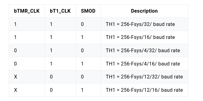
We will choose the 2nd option in the list above and set TH1 register for 9600 baud rate.
| |
Now, we will start the timer1 by setting the TR1 bit. Set the transmit interrupt flag TI for UART0. and enable the UART0 by setting REN bit in the SCON register.
| |
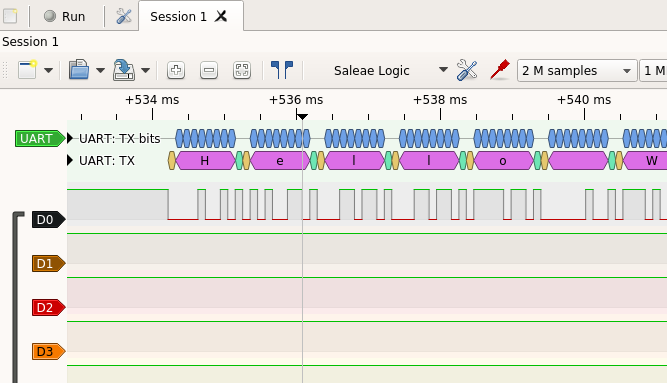
Sending Data to UART0
We can send data via UART0 by writing on the SBUF register.
| |
Receiving Data from UART0
We can receive data from UART0 by reading the SBUF register.
| |
Using printf with UART0
Redirecting stdout is easy with SDCC
| |
Now we can use printf() for debugging.