CH559 Programming (Part 5): Working with GPIO
 In this part, we will go through GPIO in detail. we had briefly touched upon GPIOs in our first tutorial. Now we will rewrite the LED blink example in a more structured way later in this tutorial.
CH559 has 45 I/O pins, some of them have alternative functions. All the GPIOs are group into ports of up to 8 pins. P0 to P3 all registers for the GPIO are bit addressable. There are a P4 and P5 in Ch559 but will talk about them in future tutorials.
GPIO Registers
There is mainly one power configuration register(PORT_CFG) for P0~P3 and three configuration registers for each port. Let’s start with the PORT_CFG register, what it does and how we can configure it.
Here is the snippet from Datasheet.
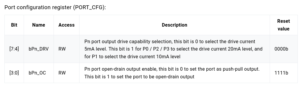
The register bits are divided into two parts. lower 4 bits(bPn_OC) are for configuring output mode and upper 4 bits(bPn_DRV) are for configuring output current for each port. If you are wondering what Push-Pull and Open-Drain are then you can check this article.
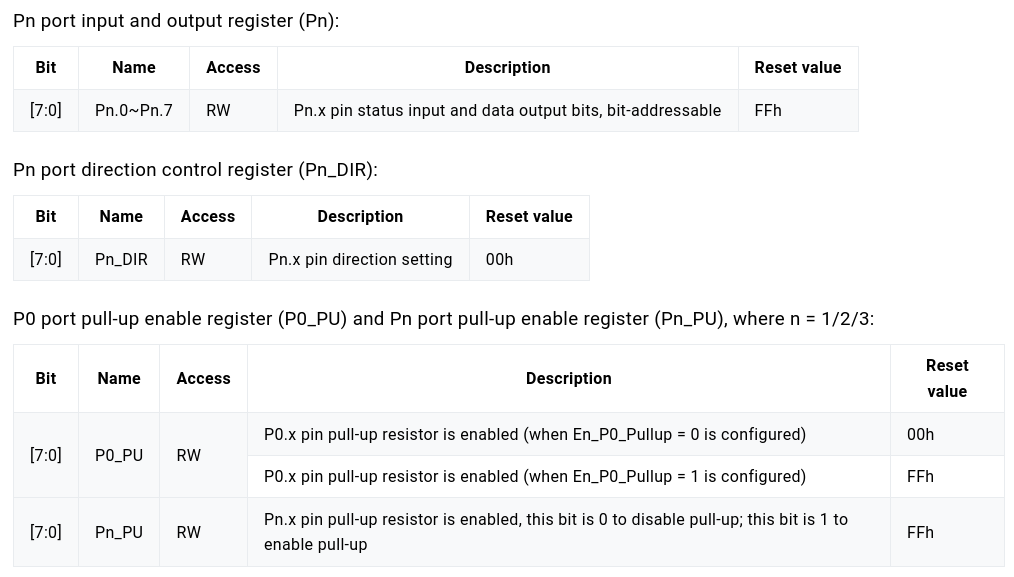
Next are the Pn, Pn_DIR, and P0=n_PU registers. Again, from the Datasheet, we can see what these registers do. All registers and bits in this section are expressed in a common format: the lowercase “n” represents the serial number of the port (n = 0, 1, 2, 3), and the lowercase “x” represents the serial number of the bit (x = 0, 1, 2, 3, 4).
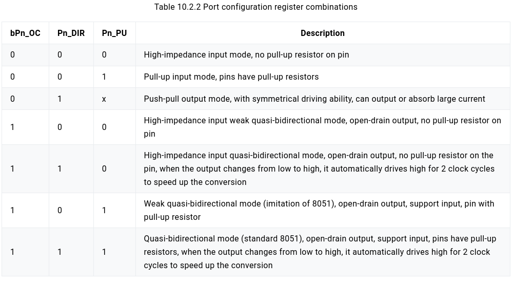
The configuration of the Pn port is implemented by the combination of the bit bPn_OC in the PORT_CFG, the port direction control register Pn_DIR, and the port pull-up enable register Pn_PU, as follows.
Making an Advanced Blinky
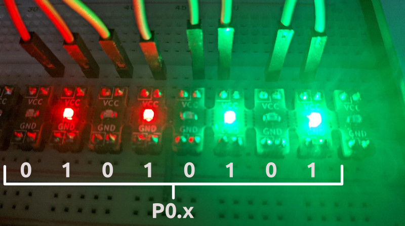
We will make a LED blink example that has 8 LEDs and will drive it using port P0 of CH559. Copy the LED blink example from the Part-2 tutorial and rename it to advance_blink. Open the main.c file and make the following changes.
| |
Congratulations! We’ve just written yet another LED blink example.